
Hello Everyone,
I apologize for not posting an update after the CleanTech Open Western Academy. I had a few personal trips, and since then I have been in an accounting abyss (related to our fund raising effort). I had promised a fuller reporting of the CleanTech Open, but I will have to defer that update for later.
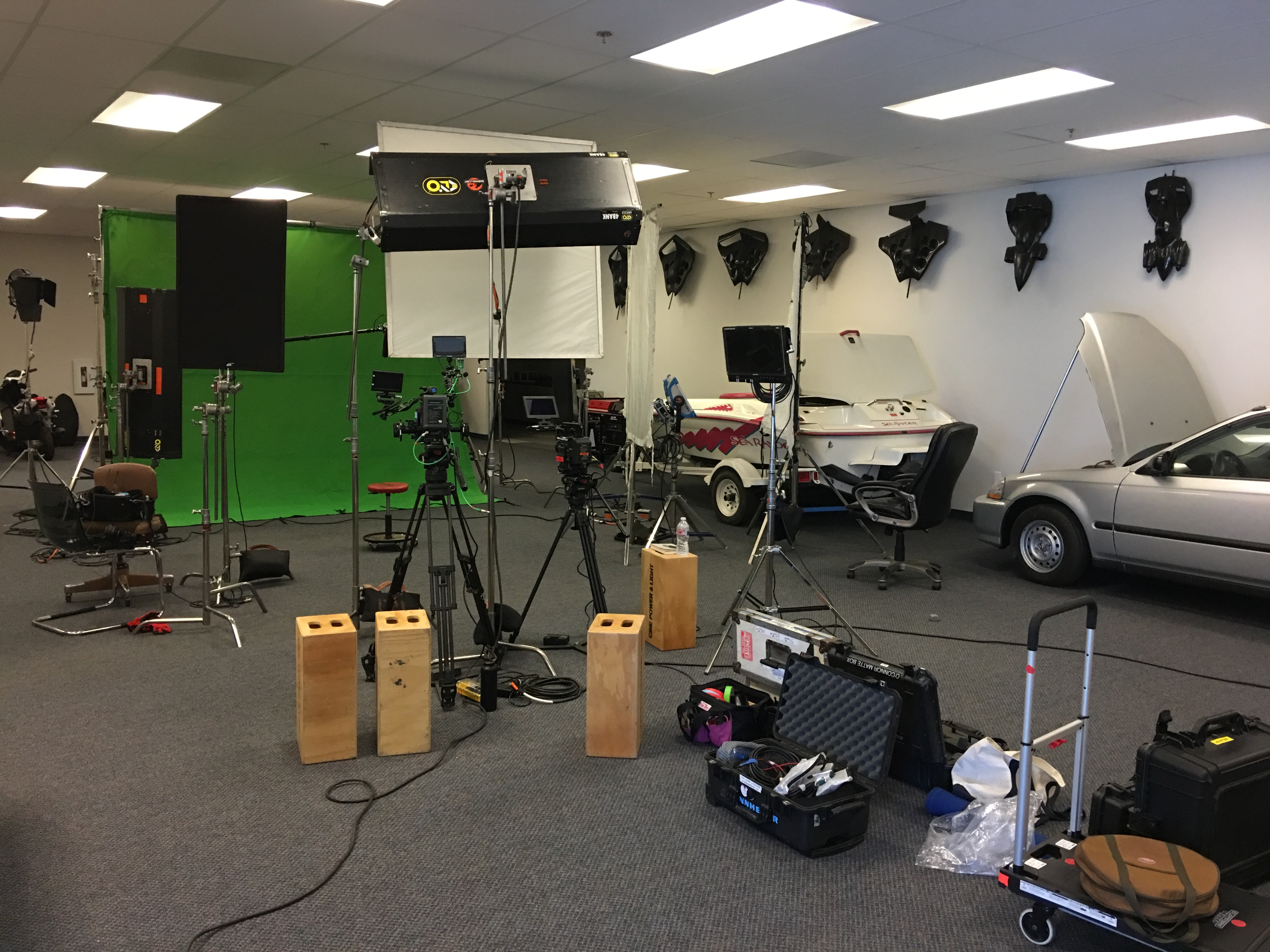
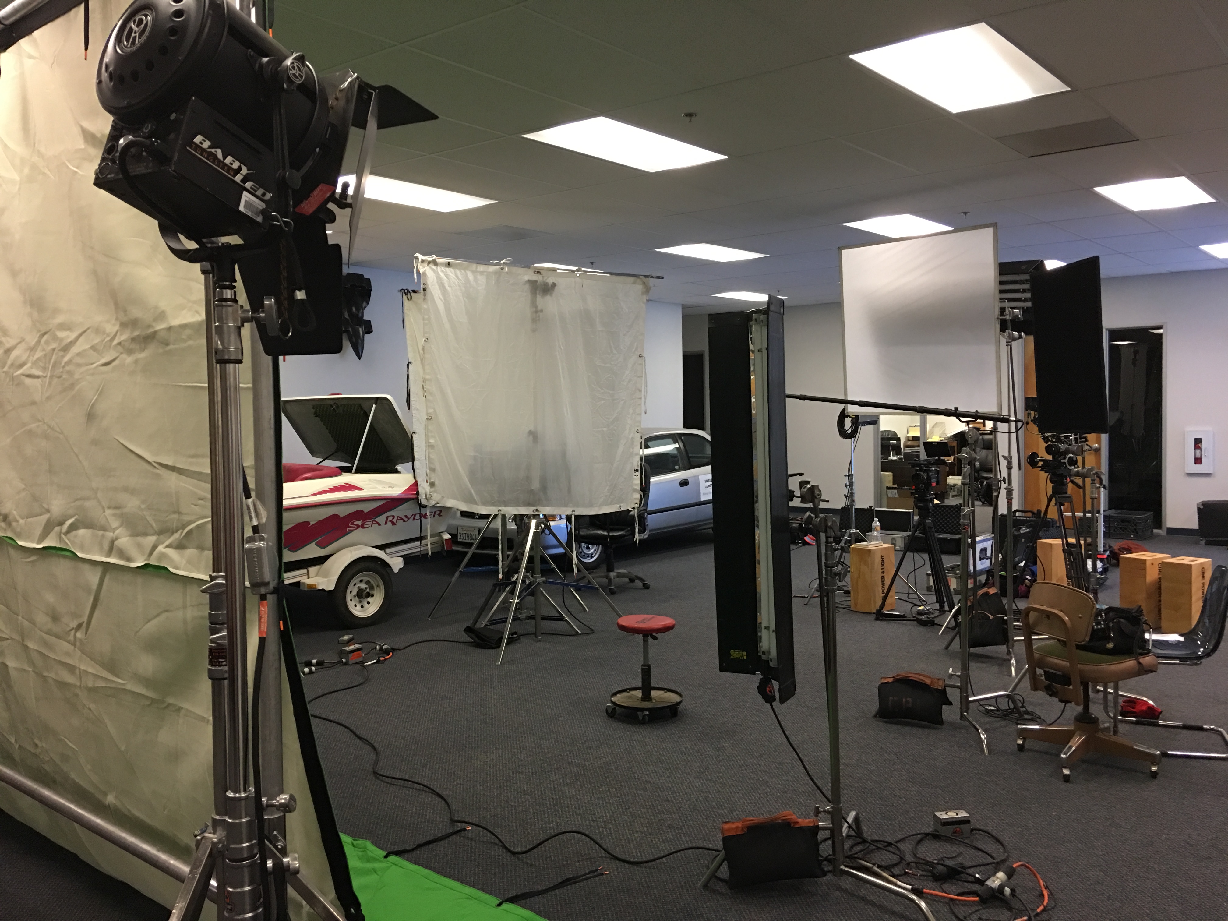
We did a corporate video, and I am including a few pics showing setup at our facility. We hired a team from L.A. who helped create the video for us. It is complete and I will be sharing the video very soon with everyone – it came out really well. I cannot share it today because of SEC rules.
 George Stevens has been working hard to put together an engine for our prototype biogas generator, and he has now completed the build. Because this engine must include all our latest IP, he had to chose from our existing stock of prototype components, most of which have been used in R&D over the years. Therefore he was burdened with extra inspection work to verify that all the components were meeting our production specifications. As of now, he only has to add the intake port connector and the capacitive discharge system for the spark plug. We will be shipping it out shortly to our business partner for building up the rest of the generation system. I included a few pics below of the engine for you to see.
Yes it looks a bit beat up – that is because this engine has gone through a lot of modifications and testing over the years. In fact, it is one of the engine housings used in the Skycar M400 hover tests.
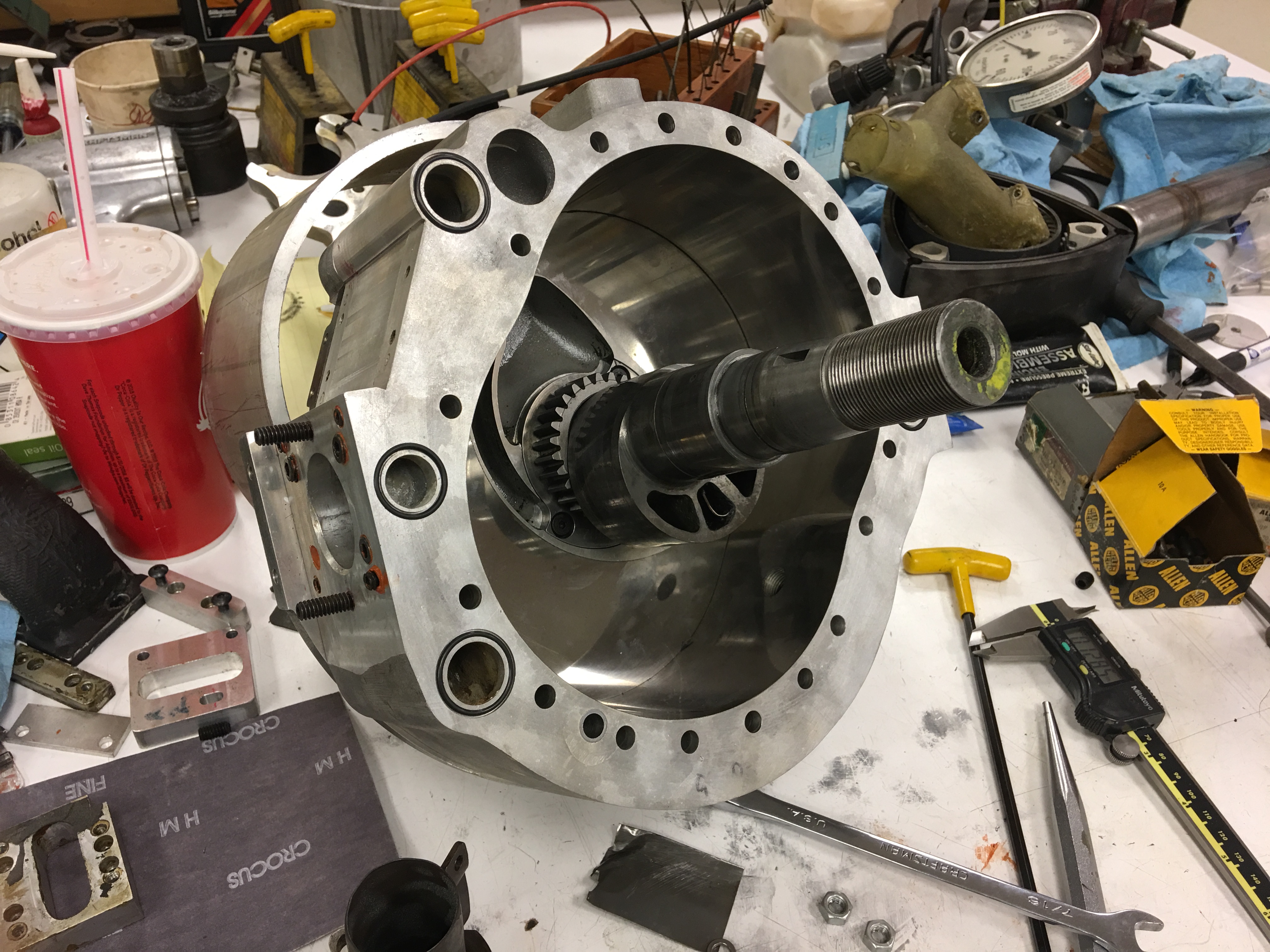
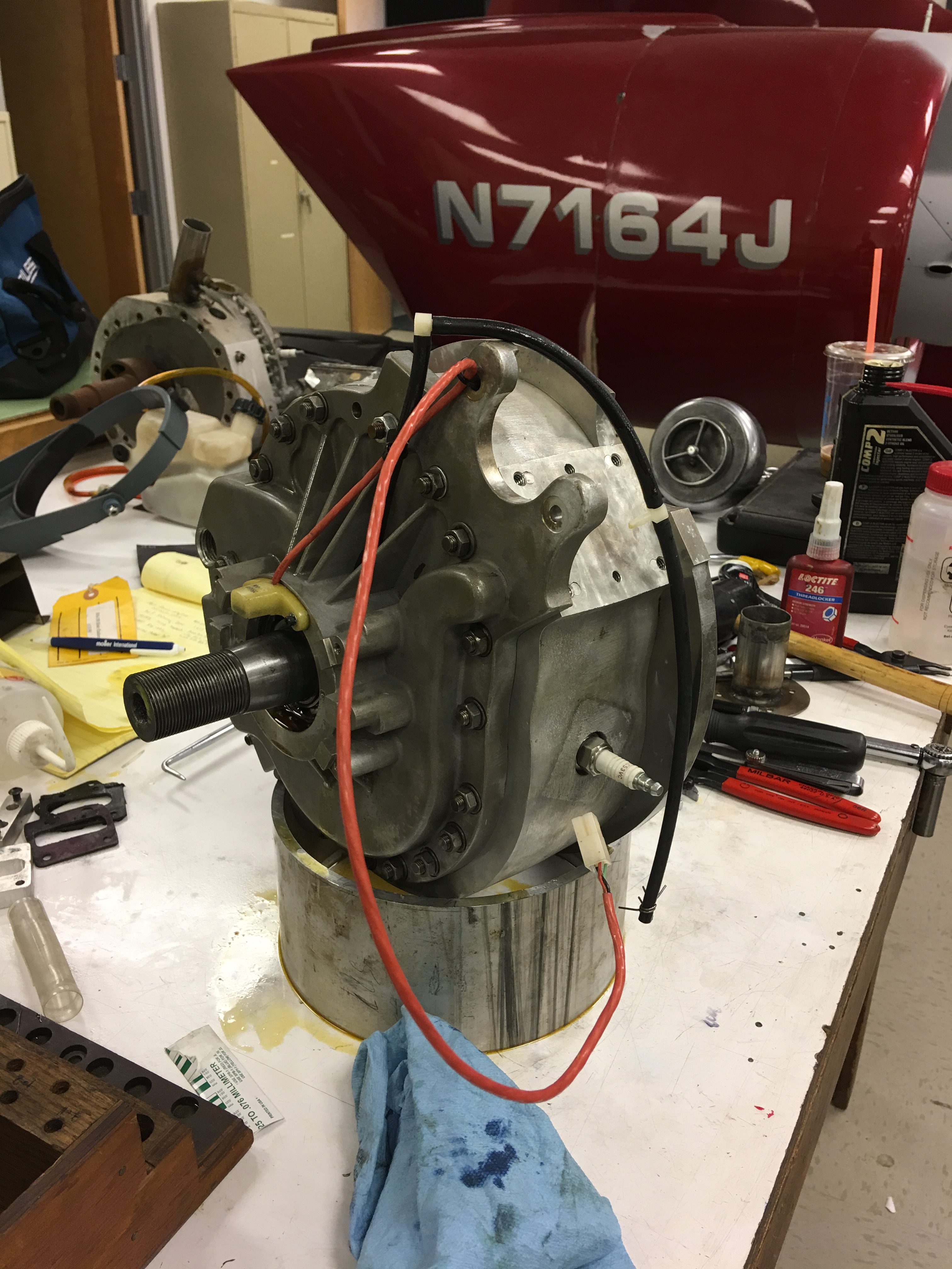
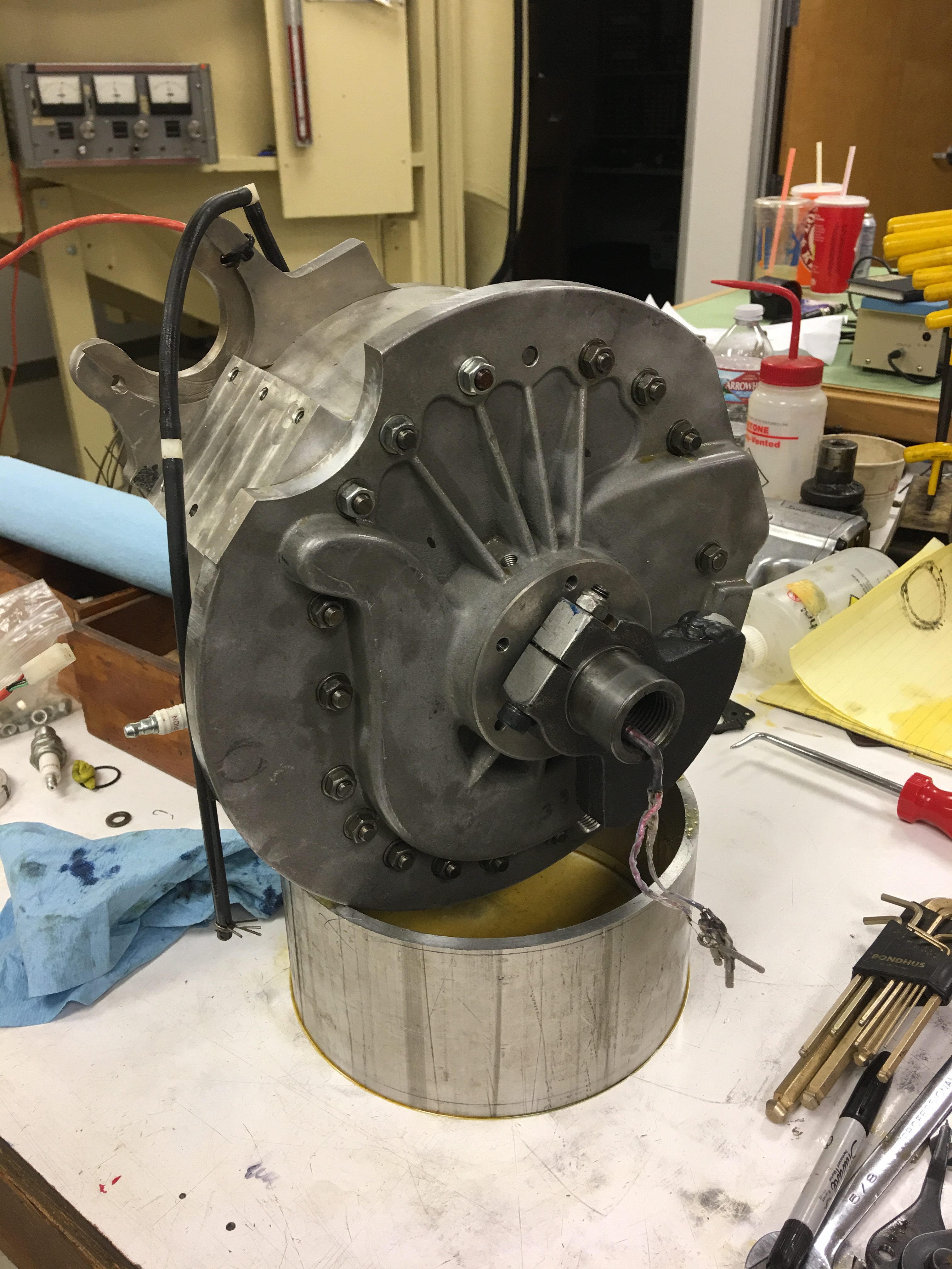
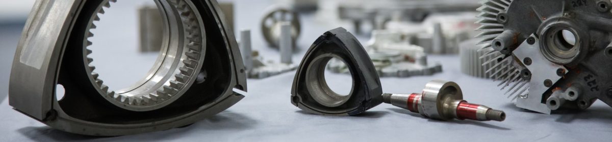
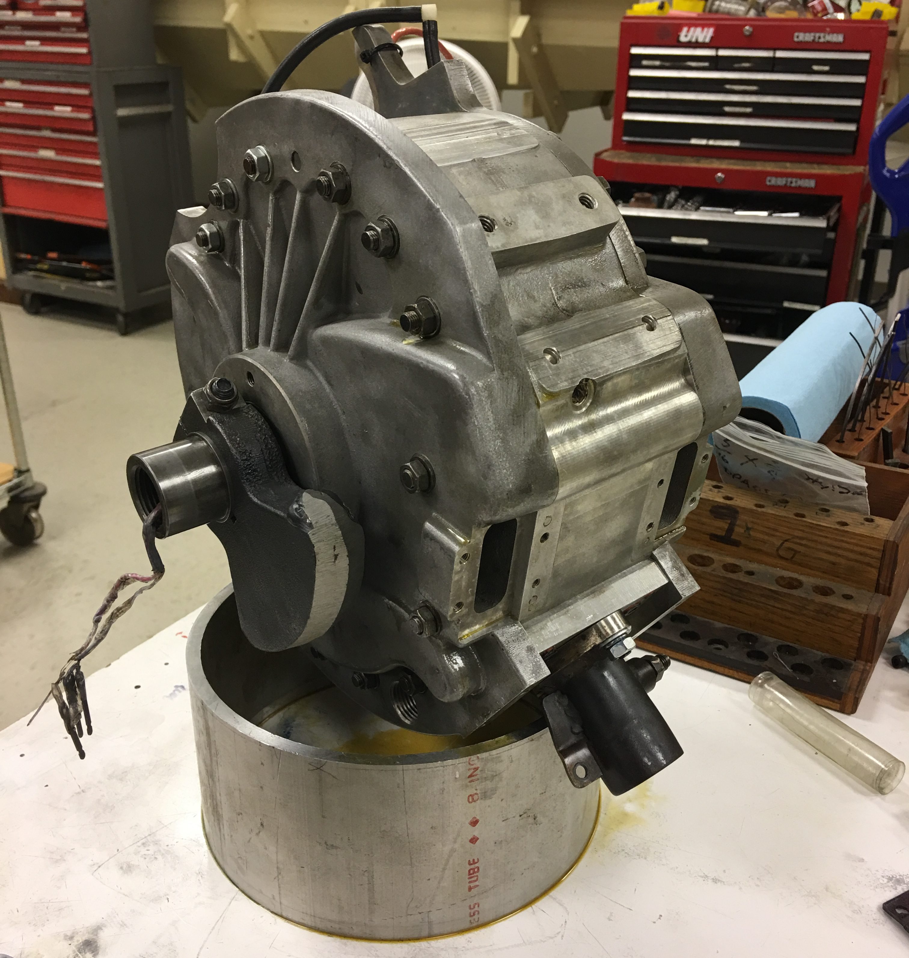 The two sets of wires coming out of the end of the drive shaft are for thermocouples embedded in eccentric portion of the shaft. We have to monitor internal rotor temperature because we are unsure how much water will be needed to cool the rotor when running on biogas. Too much water, you quench combustion and loose too much power. Too little water, and the rotor will overheat. The FM engines utilize the heat evaporation of the fuel to cool the rotor (same as OMC), but because biogas is already a gas, you have to add some liquid to the air/fuel charge to cool the rotor.
The small black tube on the bottom right is the exhaust port. The two small rectangular openings just above the exhaust port are the incoming air/fuel charge ports – these go into the end housings, filter through the middle of the rotor before entering the combustion chamber for compression.
That’s all for now, just a quick update. Look for some announcements this coming week!
Regards – Dave